hi_isp_slave_sns_sync
说明
定义从模式 sensor 同步信号配置。
定义
typedef struct {
    union {
        struct {
            hi_u32    bit16_reserved : 16;
            hi_u32    bit_h_inv : 1;
            hi_u32    bit_v_inv : 1;
            hi_u32    bit12_reserved : 12;
            hi_u32    bit_h_enable : 1;
            hi_u32    bit_v_enable : 1;
        } bits;
        hi_u32 bytes;
    } cfg;
    hi_u32    vs_time;
    hi_u32    hs_time;
    hi_u32    vs_cyc;
    hi_u32    hs_cyc;
    hi_u32    hs_dly_cyc;
    hi_u32    slave_mode_time;
} hi_isp_slave_sns_sync;
成员
成员名称 |
描述 |
|---|---|
bit16_reserved |
保留字段。 |
bit_h_inv |
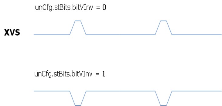
XHS极性配置。
|
bit_v_inv |
XVS极性配置。
|
bit12_reserved |
保留字段。 |
bit_h_enable |
XHS输出使能。 |
bit_v_enable |
XVS输出使能。 |
vs_time |
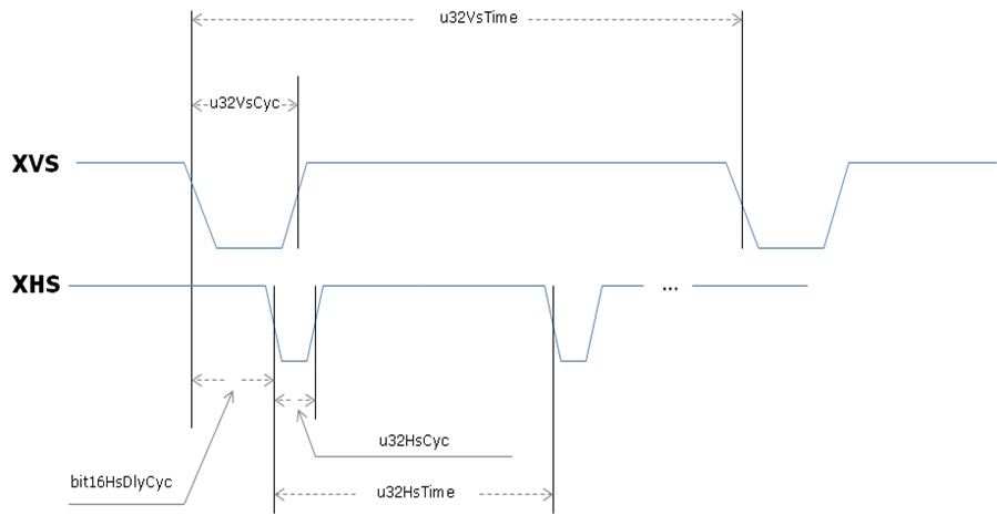
XVS信号周期,单位:sensor输入时钟周期。 |
hs_time |
XHS信号周期,单位:sensor输入时钟周期。 |
vs_cyc |
XVS有效电平宽度,单位:sensor输入时钟周期。 |
hs_cyc |
XHS有效电平宽度,单位:sensor 输入时钟周期。 |
hs_dly_cyc |
XHS脉冲输出相对XVS脉冲的延迟周期配置,单位:sensor输入时钟周期。 |
slave_mode_time |
Sensor从模式时序配置选择寄存器:
|
注意事项
如图 2-4~图 2-6 所示,说明了同步信号发生模块配置参数的含义。
图2-4 同步信号配置时序图

图2-5 同步信号极性翻转

图2-6 同步信号使能

父主题: ISP系统控制及3A算法注册数据类型